
Project
Chemical Skin: Printing on Complex Surfaces
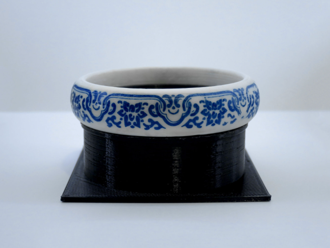
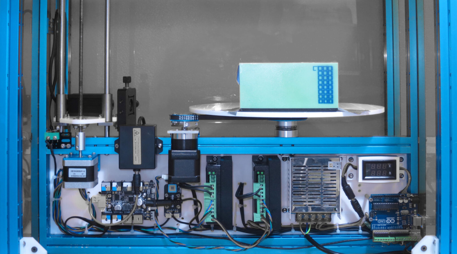
Precise printing on complex surfaces has always been a challenge. Only until recently, advancement in robotically actuated hydroprinting and models of liquid film distortion enabled precise registration of images onto complex 3D objects. However, it has its own limitation where concave hulls on objects are not printable. This project proposes a novel approach by coating objects with a photosensitive chemical, eliminating the need for an intermediate transfer medium. Utilizing collimated laser light, precise exposure of the chemicals is achieved, circumventing the issue of varying projection distances. This contact-free method allows printing in hard-to-reach areas, provided they are accessible to laser light.
In collaboration with Tobias KLEIN and supported by research assistants, my role encompassed the mechatronics design, machine construction, laser system design, development of machine control firmware, and CAD to CAM software, alongside the chemical formulation and process engineering for the photosensitive procedure.
#Printing
2023
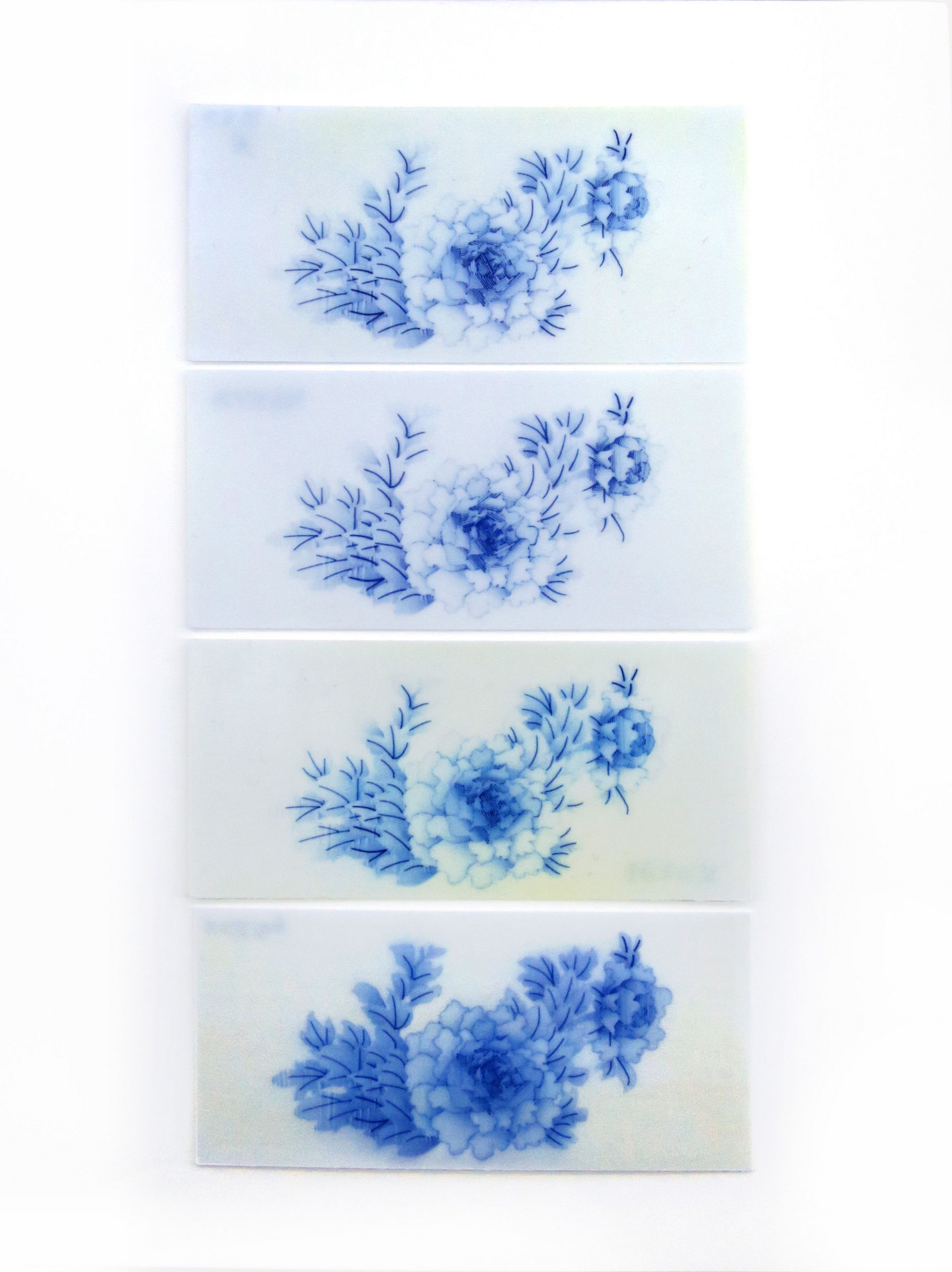
The following image shows tests conducted to validate the effect of different laser power and speed settings. Gradient effect was achieved by a irregular hatching process with changing laser power.
Design Statement
A classical way of conceptually deconstructing a table (I am referring to deconstructivism, not the act of pulling things apart) is that you need legs that can withstand some compression and a table top that can span some distance. Since the D-Board have no problem acting as the table top, the challenge is to see if we can make the legs out of the wires.
We want our design to emphases the slenderness of the thin stainless steel rods (to be honest, 3.18mm in diameter is so thin that maybe we should call them wires instead of rods). They are pretty flexible on their own and cannot stand much compression without buckling. So we bundled four rods in a double triangular shape to form each table leg. We wanted a pointy triangular tip that touches the ground, but unfortunately the bender cannot bend acute angles, so we have to live with a 17mm wide flat bottom (see the image above: the machine just finished bending the flat bottom). Four legs arranged at the four corners of the table sufficiently held up the heaviest concrete model that is more than 10kg. (Because like every architecture school, some student will cast a concrete model for the sake of it)
We entertained the idea of making a truss structure out of the wires, creating a very strong leg, but that would not have been this beautiful. We also tested if we can weld the 304 Stainless Steel, but I have zero experience in welding and noting fruitful came out of my experiments.
Wire to Cardboard Joint
The tricky part of this project is not just about thin legs standing up. Anyone who have made a table or a chair (that has four legs) will tell you that the connection between the legs and the table top is quite critical. We need to design a joint such that (1) loading will not cause the metal wire to puncture through the cardboard top. And (2) the joint needs to resist bending moment, otherwise the table legs will fail by spreading, way before compression failure. We also need to (3) make the joint easy to assemble and disassemble because we neither have storage space for the assembled tables nor have sufficient on-site setup time before the exhibition opens.
Yes, that is an extremely ugly prototype.
The first major joint design was to use a flat portion of the wire to distribute the load on the cardboard. (See photo below: the leg is very short to save some testing material) The four points that touches the cardboard are forcefully inserted into the board that has a half-cut. This distribution of load worked quite well because the action of forcing the wire into the half-cut slot compressed the honeycomb layer and that gave the wire a stronger bearing surface. However, the insertion jointing method did not provide much resistance against pulling out. This means that when the leg is subjected to bending, one side of the embedded wire will be pulled out from the cardboard. We could of course hot glue/tape the wire as we force it into the cardboard, but that will not allow disassembly and reuse.
The first major joint design.
The next important iteration of the joint is to embed the wire at the table edge. This allows each wire to touch the table top at two different levels, giving a tremendous amount of improvement in resisting moment. We kept the flat portion that touches the cardboard top to avoid load induced penetration but we bent the flat part outwards (instead of inwards and complete a ring shape) such that we have two hooks. These hooks then became a mechanism that resist pull-out. (Refer to the Table Corner and Leg Detail drawing below) The leg is inserted through the bottom table edge, forced into the half-cut trench of the table top, and then pushed sideways such it it locks. Simple installation, easy to disassemble, extremely strong joint. (designing this joint feels like designing an Ikea furniture)
Once we have the joints confirmed, the other development naturally follows. We designed four different table sizes that can effectively hold different content, their dimensions are governed by minimizing cutting waste of the cardboard. We also have five different table height by bending different legs. We added a central rib to our largest table and two extra legs, but I think it is not strictly necessary.
The two triangles of each leg needs to be attached together such that it forms a bundle. Or more structural speak: such that the two wires forms a right angle when viewed on plan, and that makes the wire to table join strong to moment in two different directions. Welding was not an option of us due to the lack of time and tools. In the picture below you see that we just taped it together with white fabric tape, Later on we found that even transparent tape is strong enough, so we went for that. It is hard to notice the tape unless you kneel down and look for it.
You see the tape.
You don’t see the tape.
Production Details
The production of 71 tables was a time consuming process that involved many helpers. We tried hard to optimize the process but there are bottle-necks at certain steps. Polishing the Stainless Steel rods took almost three people two days with a handheld non-orbital sander (supplier does not have better options).
Cutting the tables on the Zund cutter was 20 to 30 hours in total. I couldn’t really complain much. It is what it is.
Cleaning the notches and joints and hot gluing the table edge took three people four to five days. I think if we had cut the pieces with a slower speed and sharper blades (blade change is already quite frequent at 3 sheets per blade) we would have spend less time in cleaning them. The cleaning of the slotted hole could also potentially be done by the cutter by running some tools over it, but we didn’t have time to test that out. We had a rather nice hot glue gun borrowed from the fab lab, very fast heat up and large glue volume per minute (but we had only one, the other one is bad).
Notch for aligning the table edge when it is folded inwards.
Hot gluing the table edge and fold.
Table top completed without the legs assembled.
Bending the rods with the Di-Wire machine took 15 to 20 hours. About 1 minute per rod with 6 bends each. If there is a automatic wire cutter integrated with the machine, that could have helped. If the wire can come in at longer lengths, we can reduce some waste and saves some loading time. Ideally the machine will be really efficient if it is fed from a spool of wire and pull it through a straightener.
The Di-wire bender behaved erratically at some point and that freaked me out a little. I guess the machine is not really designed for a industrial scale production. The tech support at Pensa Labs are very responsive.
Guess whats wrong: A loosened set screw on the small pulley attached to the bending motor. Luckily I found a imperial size Hex key in the shop. (America engineers -> we are looking at you.) But seriously, that set screw is undersized.
Prefabricated table leg in bundles. Two bent piece became one table leg. Four legs for one table. Colour code for different length / table height.
Installation – Site Setup
A little recap of the production parameters:
Table Top Material: Corrugated D-Board (White Paper Core) 16mm x 2400mm x 1200 mmMachine: ZUND G3 CutterVee Cut Tool: V-Cut Tool / Z73 Blade @ 45ËšStraight Cut Tool: Pneumatic Oscillating Tool / Z61 20×1.5mm Blade (4mm left over)Table Top Sizes: 1300mm x 900mm / 900mm Square / 900mm x 490mm / 490mm Square
Table Leg Material: 304 Stainless Steel Rod Ø 3.18mm (1/8 inch) x 2740mmPolish: #400 Sanded and DegreasedTable Leg Height: 650mm / 750mm / 850mm / 950mm / 1050mmMachine: Di-Wire Wire BenderTool: Ø 3.18mm (1/8 inch) Bending Attachment
Maximum load: 15kgTable top and legs are reusable and recyclable.Exhibition Table Design Project for Singapore SUTD ASD 2016 Accreditation Exhibition
Exhibition Photos
Â
Â
Team
Design and Fabrication: Victor Leung
Project Lead: Felix Raspall
Exhibition Editor: Vedashree Jathar
Special Thanks to: Ang Yiliang/ Hui Xuan Tan / Kah Wee Lee / Li Jiayi / Tay Jenn Chong / Wang Xiao Tong / Zou Chu Chu
Posted in Architecture, Robotics


ADDRESS
School of Creative Media,
City University of Hong Kong, 18 Tat Hong Avenue, Kowloon Tong, Hong Kong
CONTACT
info@awesomelab.studio
SOCIAL
Youtube
Project
Chemical Skin: Printing on Complex Surfaces
Precise printing on complex surfaces has always been a challenge. Only until recently, advancement in robotically actuated hydroprinting and models of liquid film distortion enabled precise registration of images onto complex 3D objects. However, it has its own limitation where concave hulls on objects are not printable. This project proposes a novel approach by coating objects with a photosensitive chemical, eliminating the need for an intermediate transfer medium. Utilizing collimated laser light, precise exposure of the chemicals is achieved, circumventing the issue of varying projection distances. This contact-free method allows printing in hard-to-reach areas, provided they are accessible to laser light.
In collaboration with Tobias KLEIN and supported by research assistants, my role encompassed the mechatronics design, machine construction, laser system design, development of machine control firmware, and CAD to CAM software, alongside the chemical formulation and process engineering for the photosensitive procedure.
#Printing
2023
The following image shows tests conducted to validate the effect of different laser power and speed settings. Gradient effect was achieved by a irregular hatching process with changing laser power.
Design Statement
A classical way of conceptually deconstructing a table (I am referring to deconstructivism, not the act of pulling things apart) is that you need legs that can withstand some compression and a table top that can span some distance. Since the D-Board have no problem acting as the table top, the challenge is to see if we can make the legs out of the wires.
We want our design to emphases the slenderness of the thin stainless steel rods (to be honest, 3.18mm in diameter is so thin that maybe we should call them wires instead of rods). They are pretty flexible on their own and cannot stand much compression without buckling. So we bundled four rods in a double triangular shape to form each table leg. We wanted a pointy triangular tip that touches the ground, but unfortunately the bender cannot bend acute angles, so we have to live with a 17mm wide flat bottom (see the image above: the machine just finished bending the flat bottom). Four legs arranged at the four corners of the table sufficiently held up the heaviest concrete model that is more than 10kg. (Because like every architecture school, some student will cast a concrete model for the sake of it)
We entertained the idea of making a truss structure out of the wires, creating a very strong leg, but that would not have been this beautiful. We also tested if we can weld the 304 Stainless Steel, but I have zero experience in welding and noting fruitful came out of my experiments.
Wire to Cardboard Joint
The tricky part of this project is not just about thin legs standing up. Anyone who have made a table or a chair (that has four legs) will tell you that the connection between the legs and the table top is quite critical. We need to design a joint such that (1) loading will not cause the metal wire to puncture through the cardboard top. And (2) the joint needs to resist bending moment, otherwise the table legs will fail by spreading, way before compression failure. We also need to (3) make the joint easy to assemble and disassemble because we neither have storage space for the assembled tables nor have sufficient on-site setup time before the exhibition opens.
Yes, that is an extremely ugly prototype.
The first major joint design was to use a flat portion of the wire to distribute the load on the cardboard. (See photo below: the leg is very short to save some testing material) The four points that touches the cardboard are forcefully inserted into the board that has a half-cut. This distribution of load worked quite well because the action of forcing the wire into the half-cut slot compressed the honeycomb layer and that gave the wire a stronger bearing surface. However, the insertion jointing method did not provide much resistance against pulling out. This means that when the leg is subjected to bending, one side of the embedded wire will be pulled out from the cardboard. We could of course hot glue/tape the wire as we force it into the cardboard, but that will not allow disassembly and reuse.
The first major joint design.
The next important iteration of the joint is to embed the wire at the table edge. This allows each wire to touch the table top at two different levels, giving a tremendous amount of improvement in resisting moment. We kept the flat portion that touches the cardboard top to avoid load induced penetration but we bent the flat part outwards (instead of inwards and complete a ring shape) such that we have two hooks. These hooks then became a mechanism that resist pull-out. (Refer to the Table Corner and Leg Detail drawing below) The leg is inserted through the bottom table edge, forced into the half-cut trench of the table top, and then pushed sideways such it it locks. Simple installation, easy to disassemble, extremely strong joint. (designing this joint feels like designing an Ikea furniture)
Once we have the joints confirmed, the other development naturally follows. We designed four different table sizes that can effectively hold different content, their dimensions are governed by minimizing cutting waste of the cardboard. We also have five different table height by bending different legs. We added a central rib to our largest table and two extra legs, but I think it is not strictly necessary.
The two triangles of each leg needs to be attached together such that it forms a bundle. Or more structural speak: such that the two wires forms a right angle when viewed on plan, and that makes the wire to table join strong to moment in two different directions. Welding was not an option of us due to the lack of time and tools. In the picture below you see that we just taped it together with white fabric tape, Later on we found that even transparent tape is strong enough, so we went for that. It is hard to notice the tape unless you kneel down and look for it.
You see the tape.
You don’t see the tape.
Production Details
The production of 71 tables was a time consuming process that involved many helpers. We tried hard to optimize the process but there are bottle-necks at certain steps. Polishing the Stainless Steel rods took almost three people two days with a handheld non-orbital sander (supplier does not have better options).
Cutting the tables on the Zund cutter was 20 to 30 hours in total. I couldn’t really complain much. It is what it is.
Cleaning the notches and joints and hot gluing the table edge took three people four to five days. I think if we had cut the pieces with a slower speed and sharper blades (blade change is already quite frequent at 3 sheets per blade) we would have spend less time in cleaning them. The cleaning of the slotted hole could also potentially be done by the cutter by running some tools over it, but we didn’t have time to test that out. We had a rather nice hot glue gun borrowed from the fab lab, very fast heat up and large glue volume per minute (but we had only one, the other one is bad).
Notch for aligning the table edge when it is folded inwards.
Hot gluing the table edge and fold.
Table top completed without the legs assembled.
Bending the rods with the Di-Wire machine took 15 to 20 hours. About 1 minute per rod with 6 bends each. If there is a automatic wire cutter integrated with the machine, that could have helped. If the wire can come in at longer lengths, we can reduce some waste and saves some loading time. Ideally the machine will be really efficient if it is fed from a spool of wire and pull it through a straightener.
The Di-wire bender behaved erratically at some point and that freaked me out a little. I guess the machine is not really designed for a industrial scale production. The tech support at Pensa Labs are very responsive.
Guess whats wrong: A loosened set screw on the small pulley attached to the bending motor. Luckily I found a imperial size Hex key in the shop. (America engineers -> we are looking at you.) But seriously, that set screw is undersized.
Prefabricated table leg in bundles. Two bent piece became one table leg. Four legs for one table. Colour code for different length / table height.
Installation – Site Setup
A little recap of the production parameters:
Table Top Material: Corrugated D-Board (White Paper Core) 16mm x 2400mm x 1200 mmMachine: ZUND G3 CutterVee Cut Tool: V-Cut Tool / Z73 Blade @ 45ËšStraight Cut Tool: Pneumatic Oscillating Tool / Z61 20×1.5mm Blade (4mm left over)Table Top Sizes: 1300mm x 900mm / 900mm Square / 900mm x 490mm / 490mm Square
Table Leg Material: 304 Stainless Steel Rod Ø 3.18mm (1/8 inch) x 2740mmPolish: #400 Sanded and DegreasedTable Leg Height: 650mm / 750mm / 850mm / 950mm / 1050mmMachine: Di-Wire Wire BenderTool: Ø 3.18mm (1/8 inch) Bending Attachment
Maximum load: 15kgTable top and legs are reusable and recyclable.Exhibition Table Design Project for Singapore SUTD ASD 2016 Accreditation Exhibition
Exhibition Photos
Â
Â
Team
Design and Fabrication: Victor Leung
Project Lead: Felix Raspall
Exhibition Editor: Vedashree Jathar
Special Thanks to: Ang Yiliang/ Hui Xuan Tan / Kah Wee Lee / Li Jiayi / Tay Jenn Chong / Wang Xiao Tong / Zou Chu Chu
Posted in Architecture, Robotics


ADDRESS
School of Creative Media, City University of Hong Kong, 18 Tat Hong Avenue, Kowloon Tong, Hong Kong
CONTACT
info@awesomelab.studio
SOCIAL
Youtube